Table of Contents
uTerm2-S
Description
I wanted an “advanced” legacy RS232 video terminal to play with “retro stuff”, so I decided to try out the FabGL library with an ESP32 (ESP32-Wroom-32) module.
Details
Hardware Overview
The uTerm2-S (micro Term2 Stand-alone) is an easy to build multi-emulation RS232 terminal using an ESP32-Wroom-32 module and the great FabGL library.
More, using an ESP32 gives the opportunity to use the uTerm2-S in a lot of different ways easily using the Arduino IDE with the ESP32 core.
These the main specs of uTerm2-S:
- RS232 serial port;
- VGA output;
- “transparent” port for a serial-USB adapter (as in the uTerm-S);
- secondary serial port for ESP32 programming using a serial-USB adapter;
- RTS/CTS support between the RS232 and the “transparent” port (as in the uTerm-S);
- on board power supply;
- colors, graphics and sounds capabilities (FabGL library);
- multi language keyboard support (FabGL library);
- various terminal emulations (FabGL library);
- PS/2 connectors for keyboard and mouse;
- on board amplifier for an external speaker.
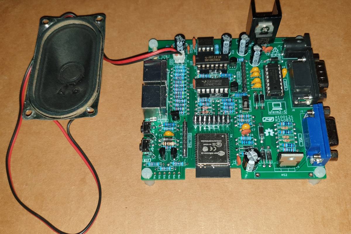
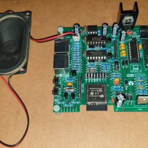
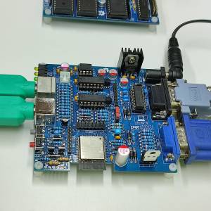
In the following image a uTerm2-S (previous PCB revision) connected to a common PC speaker:
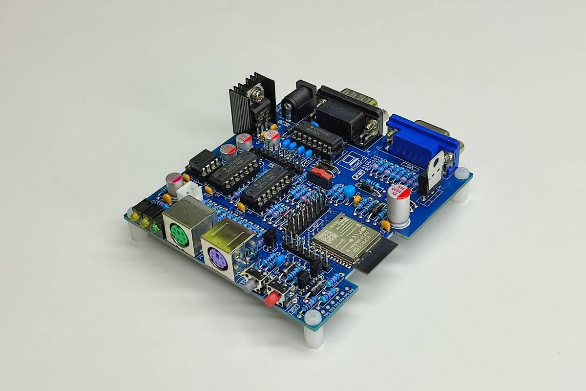
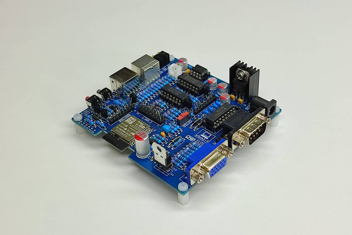
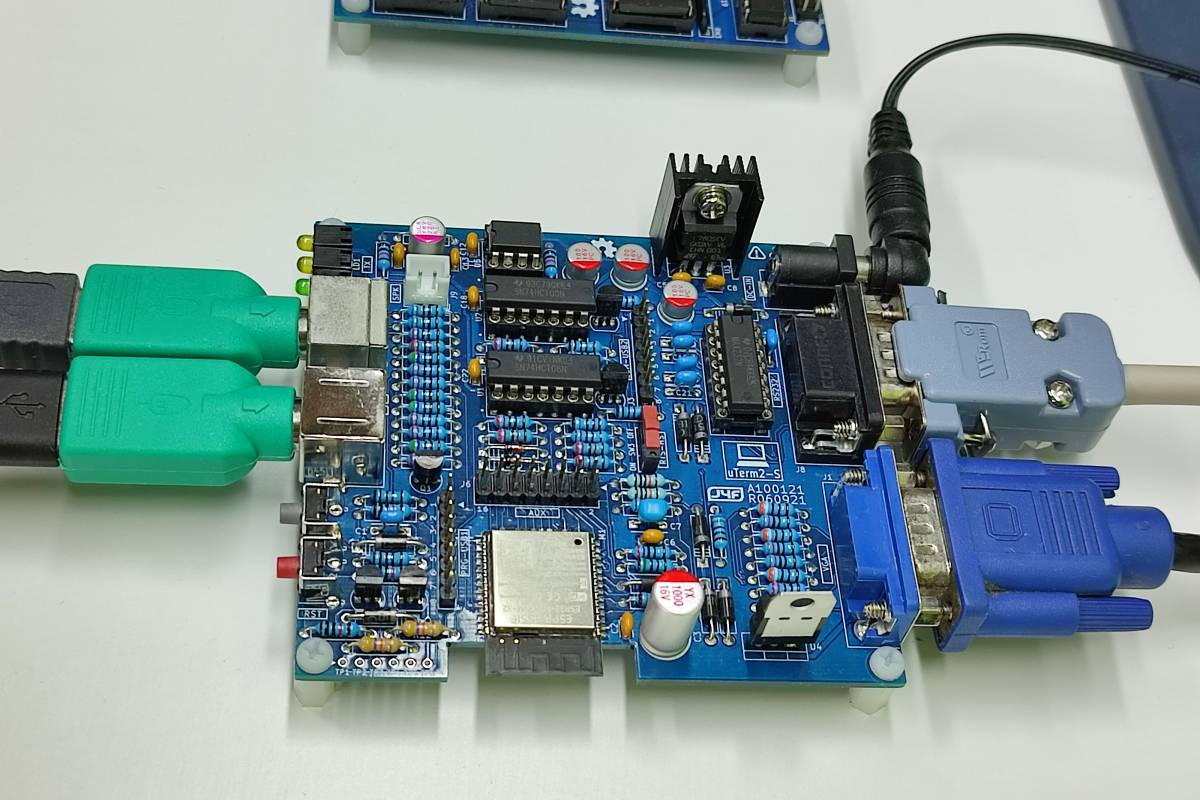
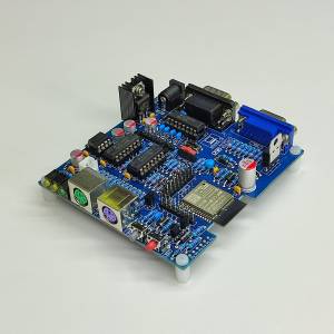
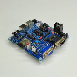
This one is the final board:
The COM-USB2 (J3) connector (Trasparent port)
The uTerm2-S has a “transparent” port for an USB-serial adapter (as in the uTerm-S), so you can e.g. use XMODEM to exchange files with a PC (running a terminal emulator that supports XMODEM file transfer) while the uTerm2-S is in use.
Both the “mixed” power supply scenarios (USB-serial adapter not powered from USB but uTerm2-S powered and vice-versa) are managed by the HW, so you don't need to worry about it.
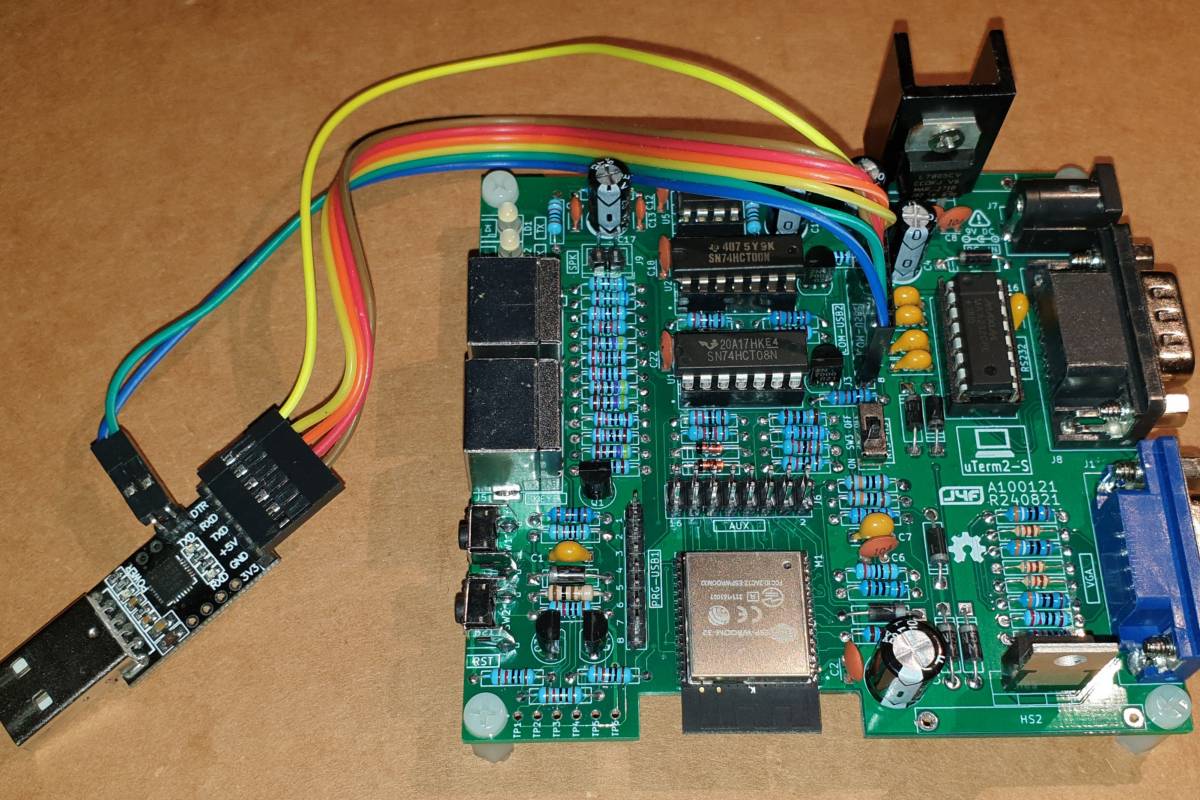
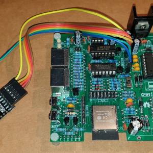
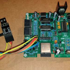
In the following photo a serial-USB adapter is connected with a cable to the transparent COM-USB2 (J3) port:
This allows to use two keyboards and two monitors in the “same” time (one keyboard and monitor attached directly to the uTerm2-S, and another keyboard and monitor of the terminal emulator on a PC connected with the serial-USB).
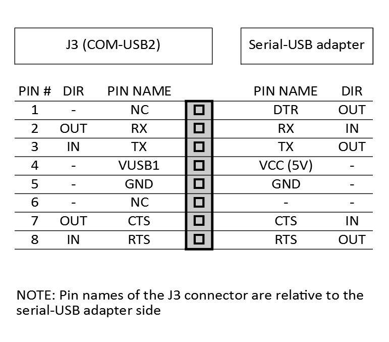
Please note that the COM-USB2 (J3) port supports the RTS/CTS HW handshaking, so both RTS/CTS signals are needed on the serial-USB adapter.
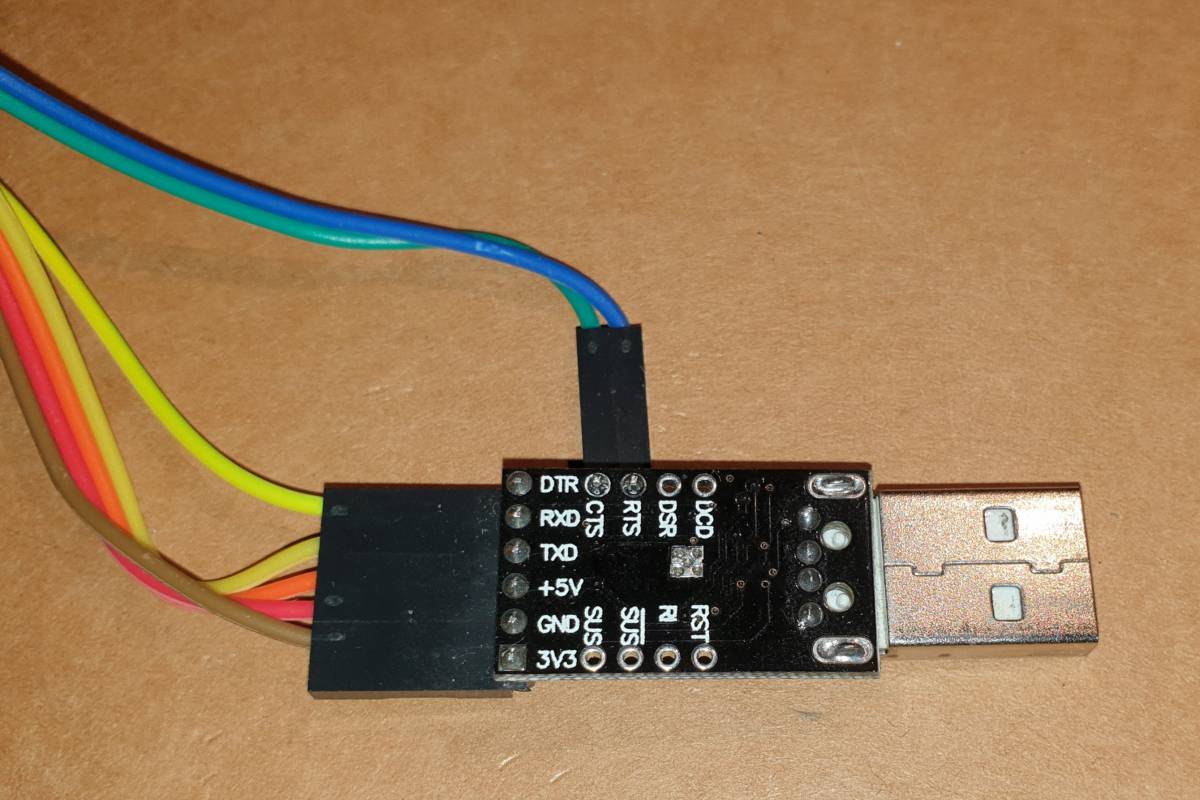
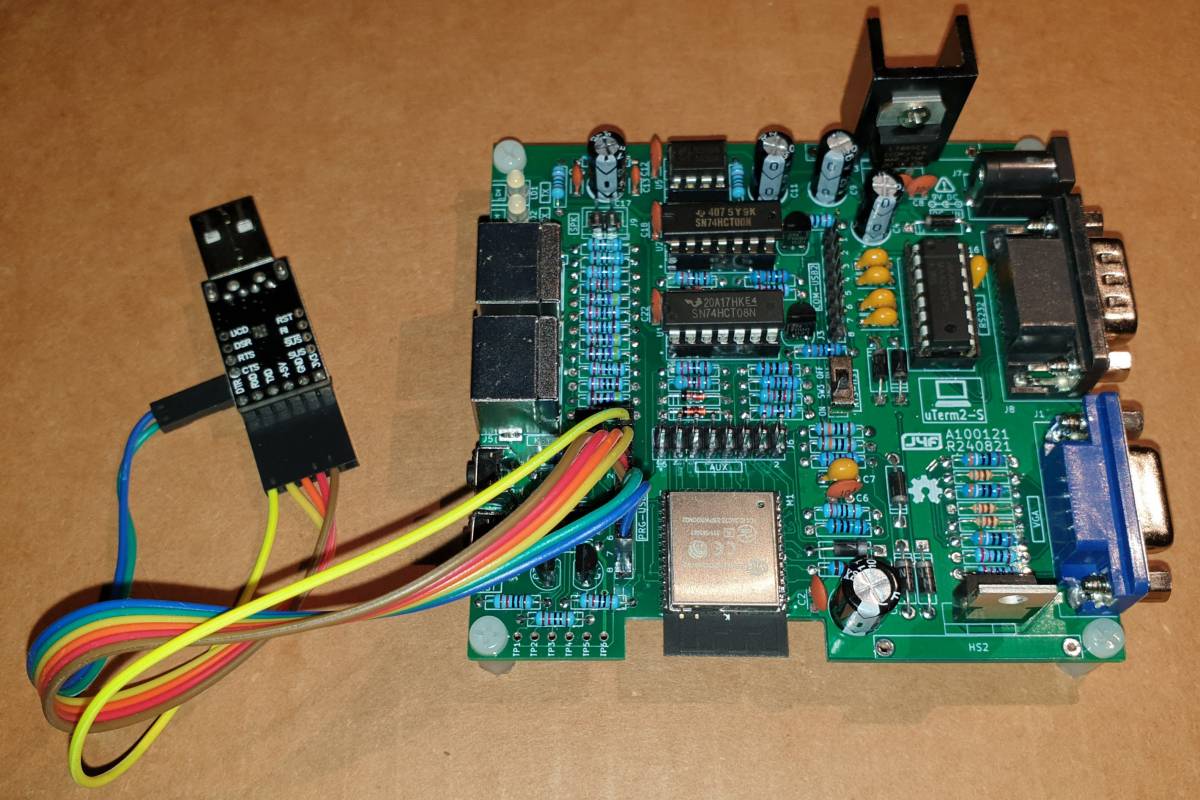
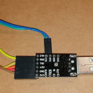
In the following image a common CP2102 based serial-USB adapter with the RTS/CTS signals connected:
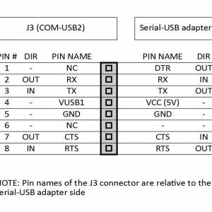
The following table shows how to connect the serial-USB adapter to J3:
NOTE: The signals assignment is the same of the SER-USB (J3) connector of the uTerm-S.
The PRG-USB1 (J2) connector (Programming port)
The PRG-USB1 (J2) connector is use to program the ESP32 using a serial-USB adapter (it is recommended to use a model that supports the default 921600 bit/s upload speed, like the CP2102 based adapters).
Both the “mixed” power supply scenarios (USB-serial adapter not powered from USB but uTerm2-S powered and vice-versa) are managed by the HW, so you don't need to worry about it.
For more information about the programming procedure see the “HOW TO PROGRAM THE ESP32” paragraph.
The SPK (J9) connector
The SPK (J9) connector is used to attach an optional speaker (4/16 Ohm). I've used a salvaged PC speaker.
Other connectors
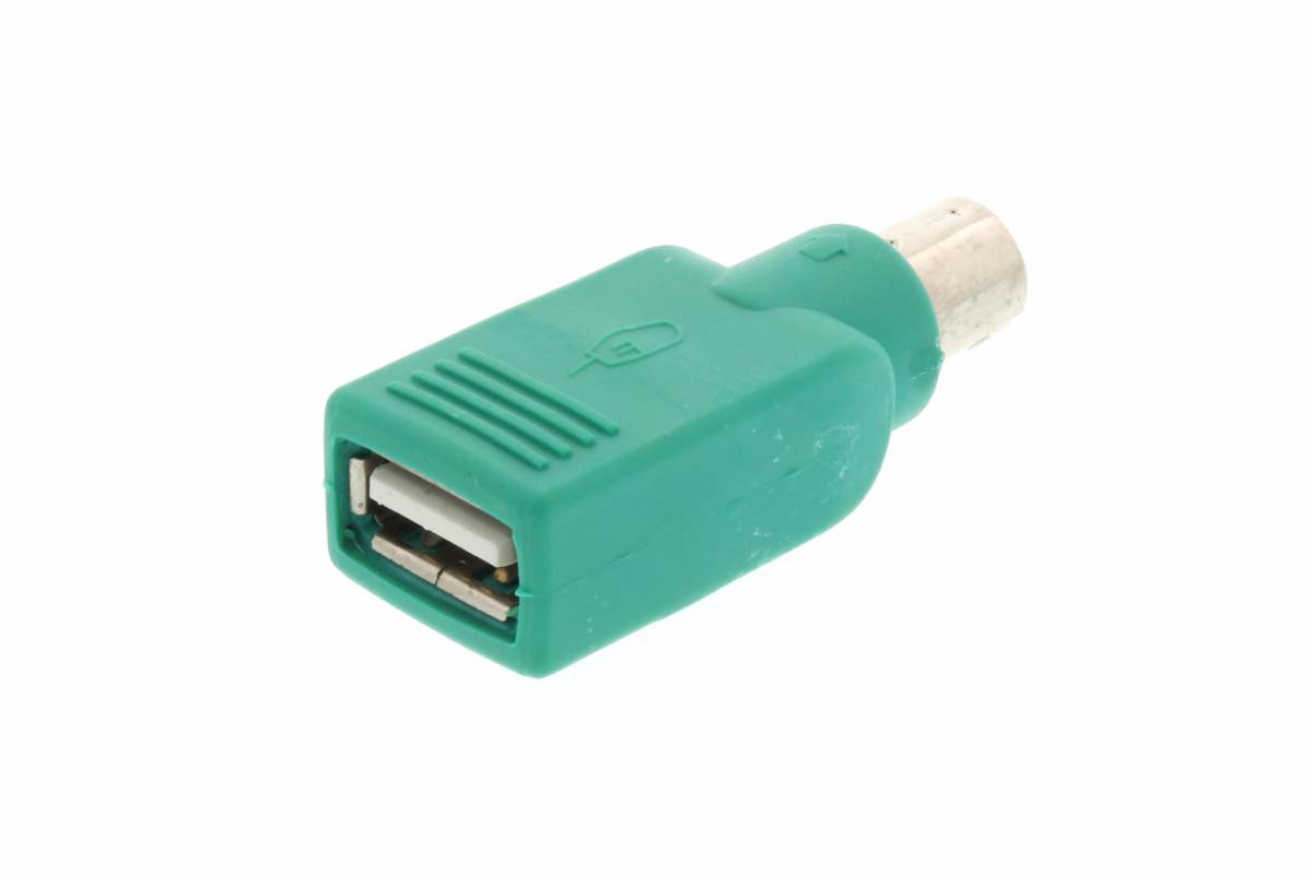
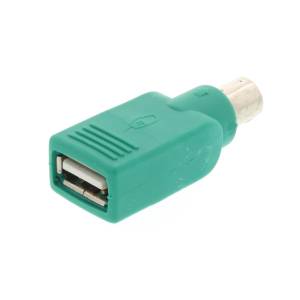
The remaining connectors are obvious. PS/2 KB (J5) and PS/2 MOUSE (J4) are for a PS/2 keyboard and an optional PS/2 mouse. Please note that many USB keyboards (and USB mouses too) have a PS/2 compatible chip inside so can be used with the well known “green adapter”:
The VGA (J1) connector is for a VGA monitor, and the RS232 (J8) connector is the RS232 serial port for the Host. The maximum speed is 115200 bps (it is the maximum speed of the MAX232 RS232 driver).
The DC-IN (J2) is the power in connector. It is recommended to use a 9V 1A DC power supply.
The RTS-HS (SW3) Switch
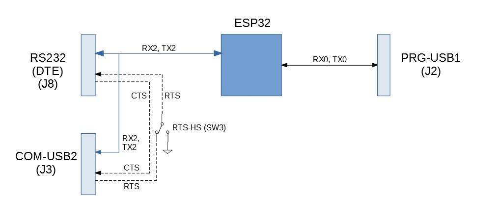
The uTerm2-S has both the RTS/CTS signals for HW handshaking between the RS232 serial port (J8) connector (for the Host) and the COM-USB2 (J3) connector (the “transparent port” for the terminal emulation SW on a PC), so it can be used for file exchange.
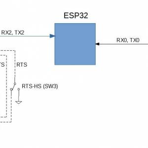
To clarify the following image shows a block diagram of the serial ports of the uTerm2-S:
On the COM-USB2 (J3) side the RTS signal is used by the terminal emulation SW on a PC to put in a wait state the communication if the RX buffer on the PC side is full. The CTS signal is an input that allows the Host to do the same if the input buffer on the Host side is full. Because a PC is typically a lot more fast than a retro-system it can be handy set the RTS signal to an “always ready to accept” state (on the PC side). In this case the RTS-HS switch (SW3) is used to turn on or off the RTS handshaking.
When turned off, the Host connected to the serial port will see the RST line always active (RTS and CTS are active “Low” signals). This can be handy in some situations.
The RTS-HS switch has no influence on the CTS signal.
The RST key (SW2)
The RST key (SW2) is used to reset the ESP32 module.
The DFLT key (SW1)
The DFLT key (SW1) is used to reset all the terminal parameters to default values. To activate this function you have to press down the DFLT key and, while holding it down until the reset is complete, press and release the RST key (SW2) to reset the uTerm2-S.
NOTE: the DFLT key must be enabled inside the AnsiTerminal sketch (see the “HOW TO PROGRAM THE ESP32 (J2/PROG-USB1 CONNECTOR)” paragraph) to make it work.
Software Overview
The uTerm2-S is designed to use the FabGL library, so you need to install Arduino IDE and the ESP32 core at first.
Then you have to install the FabGL library.
Because there are a lot of tutorials around I'll not give more details here (i.e. see the Demos and Tutorials section on the FabGL site) about how set up the “toolchain”.
How to program the ESP32
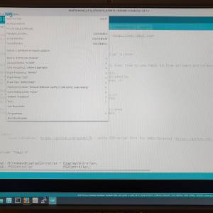
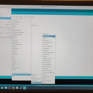
The uTerm2-S can be programmed using the Arduino IDE as a common ESP32 board (having the needed circuitry for auto uploading):
You just need to use the PRG-USB1 (J2) connector with a serial-USB adapter:
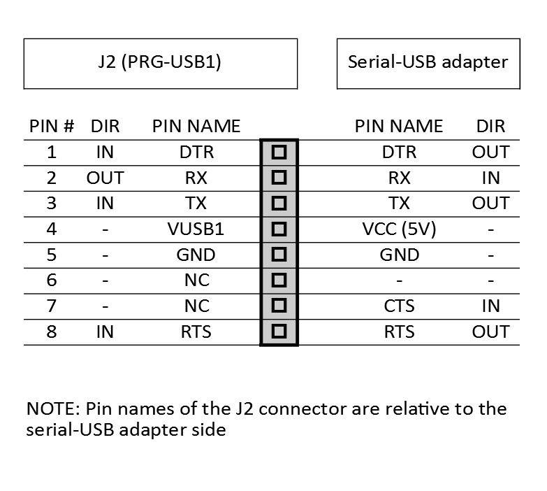
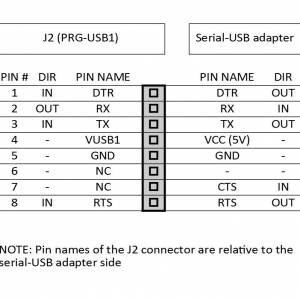
The following table shows how to connect the serial-USB adapter to PRG-USB1 (J2):
NOTE: You can use the same adapter/cable for both programming (thru J2) and communicating with the transparent port (thru J3) as the J2 and J3 connection tables have a compatible signals assignment.
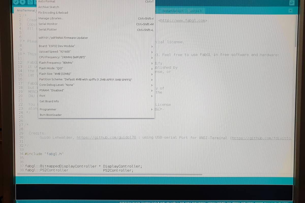
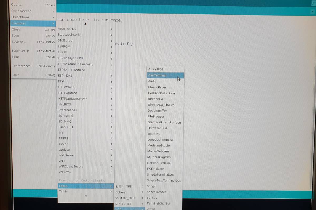
To flash the terminal FW you have to open the AnsiTerminal “sketch” from the Examples of the FabGL library:
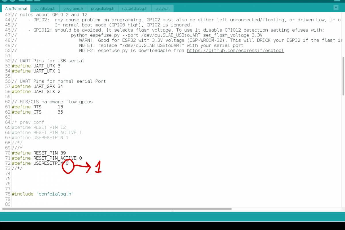
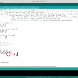
Remember to change at first the line containing:
#define USERESETPIN 0
to
#define USERESETPIN 1
to enable the DFLT key:
Now you can compile and flash the AnsiTerminal sketch.
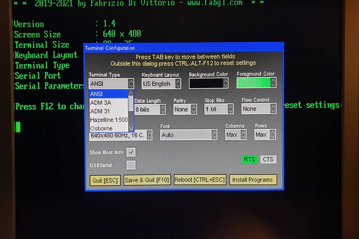
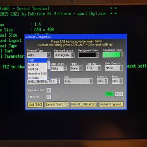
NOTE 1: Don't enable the HW RTS/CTS handshaking on the “Flow Control” terminal setting panel as the HW handshaking is reserved for the COM-USB2 (J3) “transparent” connector (see the “THE RTS-HS SWITCH” paragraph), and the relative GPIOs are not used for that.
NOTE 2: The maximum terminal serial speed cannot exceed 115200 bps.
Games
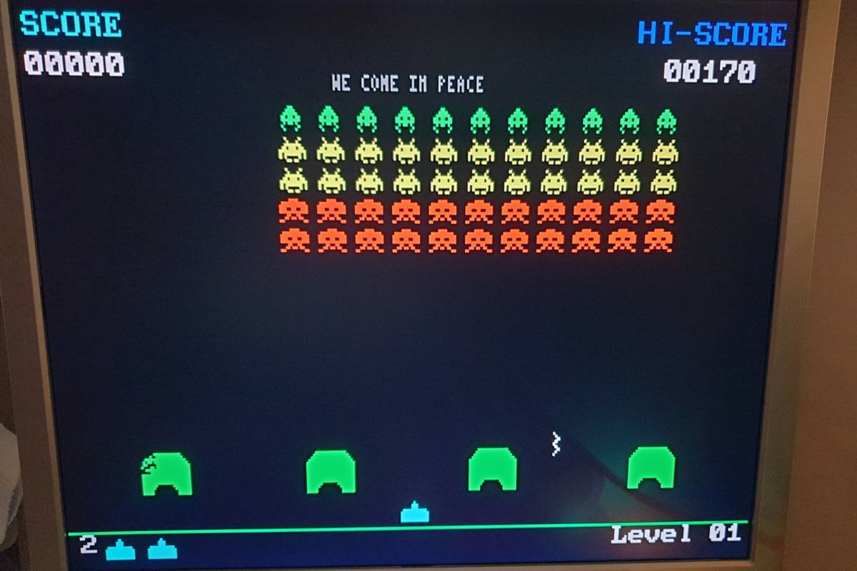
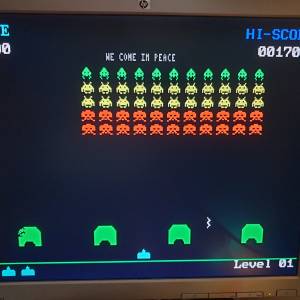
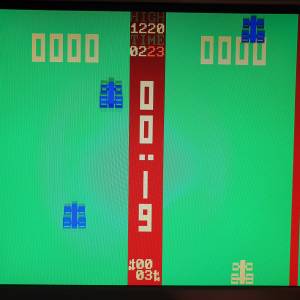
In the Examples directory of the FabGL library there are some games that can be run with the uTerm2-S too.
Here Space Invaders:
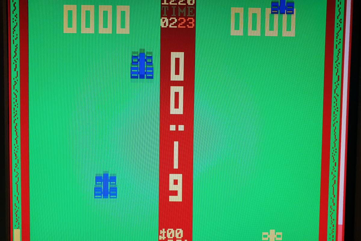
and Classic Racer:
and don't forget to connect the speaker!
How to get a PCB
I've prepared an “easy link” to order a small lot (min. 5 pcs) of PCB here.
How to get a Kit or an Assembled unit
If you are looking for a kit with all the needed parts or an assembled unit ready to use now there is a professional seller that can sell both and ship worldwide.
The link to the seller is this one.
User Group
An “User Group” was created on Facebook (it is the same used for the Z80-MBC2).
Licensing and Credits
The FabGL library was developed by Fabrizio Di Vittorio.
All the project files are licensed under GPL v3.
If you use this material in any way a reference to the author (me ☻) will be appreciated.
Files
Schematic.
A100121-R060921_SCH_v2.pdf.
BOM file.
A100121-R060921_BOM_v2.ods.
iBOM file.
A100121-R060921_iBOM_v2.zip.
PCB Gerber files (95mm x 90mm).
A100121-R060921_GBR.zip.
PCB Assembling Guide.
A100121-R060921_Assembling_Guide.zip.

